Quick Start Guide
1. Introduction
This Quick Start Guide explains the basics:
- how to connect and set up your target on the network
- how to install the SDK
- how to modify and build the firmware images
The Linux Software Developer’s Kit (SDK) is an embedded hardware and software suite that enables Linux developers to create applications on Dusun’s DSGW-081 gateway.
2. Gateway Information
This section describes the gateway’s basic resource infomation and interfaces.
2.1 Basic information
Processor: I.MX6UL (ARM32)
Supply: DC-12V/2A
RAM: DDR2 512M
EMMC: 8G
Ethernet: WAN RJ45/10M/100M
Bluetooth: ERF32BG21
Zigbee: EFR32MG1B232
LTE: BG96/EG91/..
1 User Button
1 Can
1 RS232
1 RS485
2 Analog in
2 Active In
2 Passive in
2 Digtal out
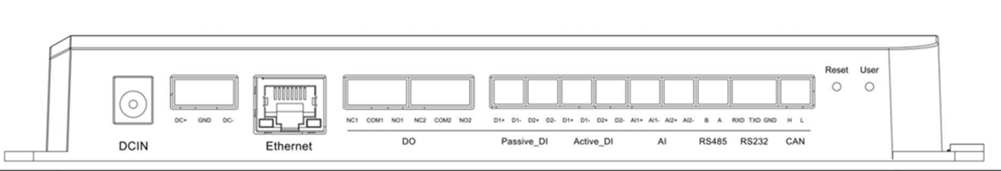
2.2 Interface
3. Debug Setup
This section describes how to connect the gateway into your host computer and network to debug for development.
3.1 Power
Make sure that the power adapter is 12V/2A.
Select the appropriate power plug adaptor for your geographical location. Insert it into the slot on the Universal Power Supply; then plug the power supply into an outlet.
Connect the output plug of the power supply to the gateway
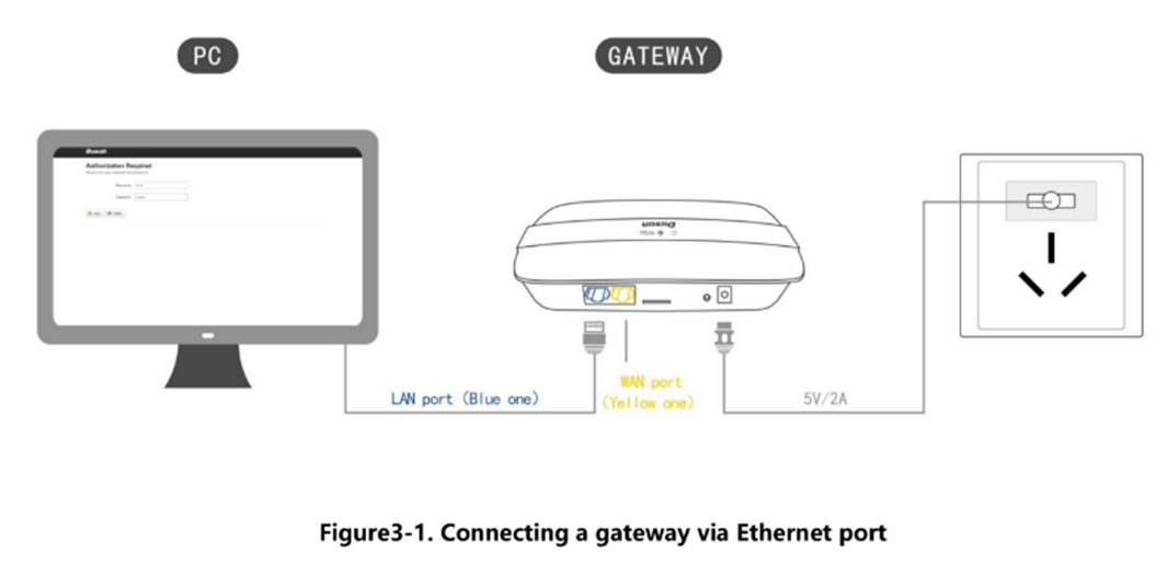
3.2 Wire Connect
Connect gateway to a router for login
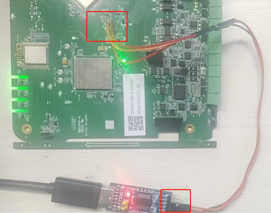
3.3 Debug Uart Connect
- Before you set up your development test bed, please connect the PCB serial port to your develop PC via USB-to-serial bridge.
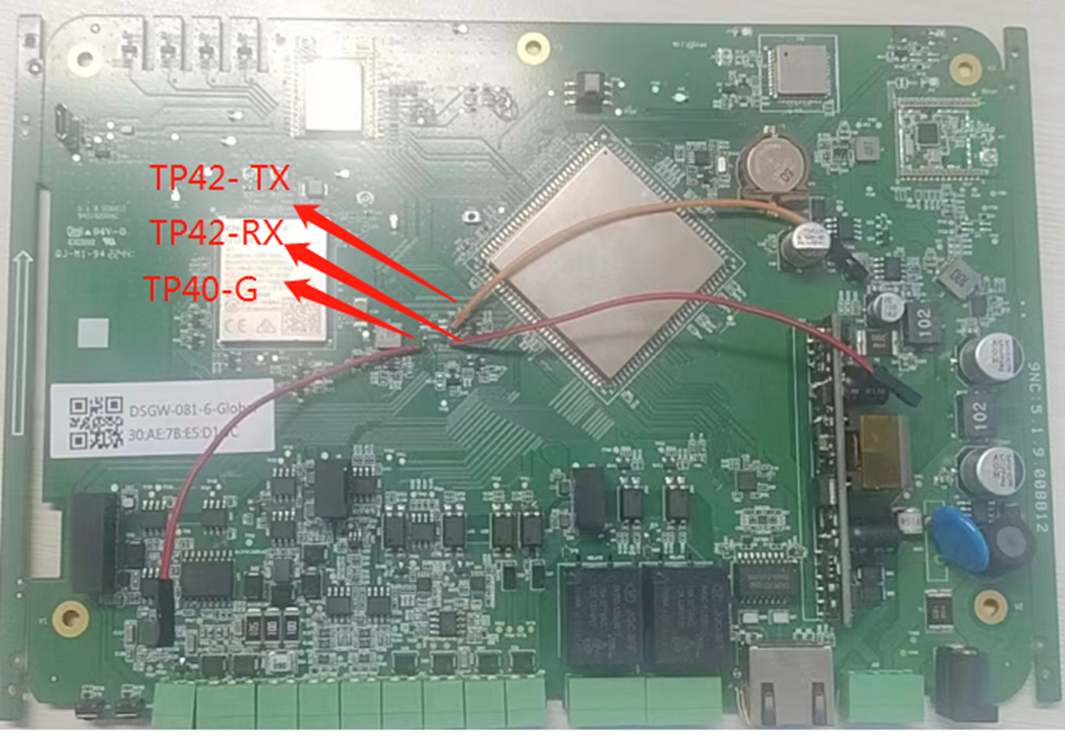
PCB serial port on Gateway
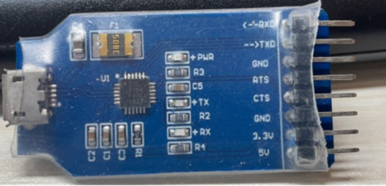
USB-to-serial bridge. Serial port setting: Baud rate: 115200 Bits: 8 Stop Bits: 1 Hardware flow control: None
4. SDK Download And Compile
This section describes how to download the sdk and compile it.
4.1 SDK Envirment Prepare
Compilation environment: Centos/Ubuntu Openwrt’s compilation tool is automatically generated by SDK built
apt install build-essential
4.1 SDK Download
Get the source code from Dusun FTP server uncompress it under your work directory. For example:
mkdir -p ~/workdir/dsgw081
tar zxvf DSGW-081_sdk_AV1.0.0.12.tar.gz -C /workdir/dsgw081
cd ~/workdir/dsgw081
4.3 SDK Compile
cd ~/workdir/dsgw081
 ./build.sh
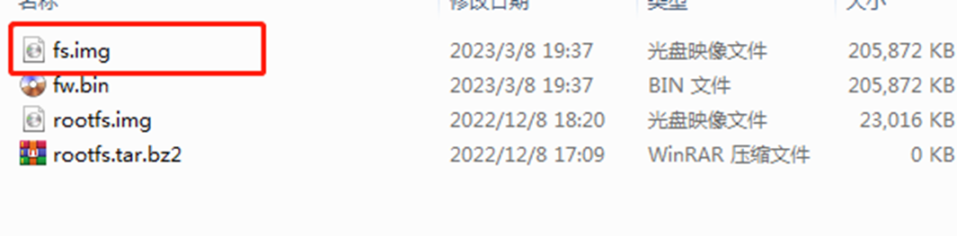
4.4 SDK Output
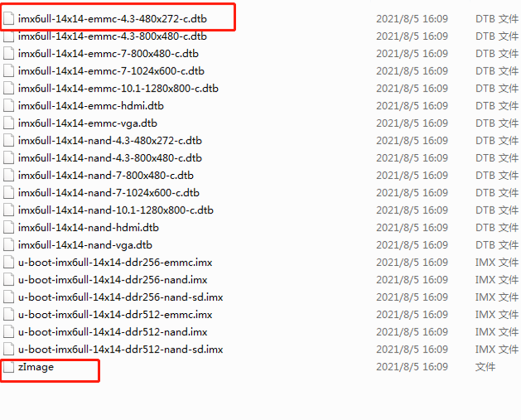
zImage is the Kernel
imx6ull-14x14-emmc-4.3-480x272-c.dtb is the dtb file
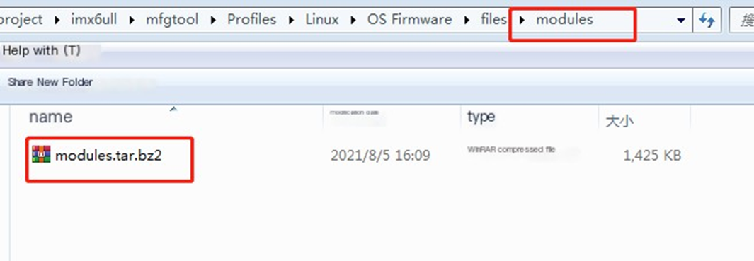
modules.tar.bz2 is kernel module file
fs.img the root filesystem
total 11M
 drwxrwxr-x 2 au au 4.0K Apr 11 16:59 .
 drwxrwxr-x 27 au au 4.0K Apr 11 16:59 ..
 -rw-rw-r-- 1 au au 34K Apr 11 16:59 DSGW-081.dtb
 -rw-rw-r-- 1 au au 39K Apr 11 16:59 imx6ull-14x14-emmc-10.1-1280x800-c.dtb
 -rw-rw-r-- 1 au au 39K Apr 11 16:59 imx6ull-14x14-emmc-4.3-480x272-c.dtb
 -rw-rw-r-- 1 au au 39K Apr 11 16:59 imx6ull-14x14-emmc-4.3-800x480-c.dtb
 -rw-rw-r-- 1 au au 39K Apr 11 16:59 imx6ull-14x14-emmc-7-1024x600-c.dtb
 -rw-rw-r-- 1 au au 39K Apr 11 16:59 imx6ull-14x14-emmc-7-800x480-c.dtb
 -rw-rw-r-- 1 au au 40K Apr 11 16:59 imx6ull-14x14-emmc-hdmi.dtb
 -rw-rw-r-- 1 au au 40K Apr 11 16:59 imx6ull-14x14-emmc-vga.dtb
 -rw-rw-r-- 1 au au 39K Apr 11 16:59 imx6ull-14x14-nand-10.1-1280x800-c.dtb
 -rw-rw-r-- 1 au au 39K Apr 11 16:59 imx6ull-14x14-nand-4.3-480x272-c.dtb
 -rw-rw-r-- 1 au au 39K Apr 11 16:59 imx6ull-14x14-nand-4.3-800x480-c.dtb
 -rw-rw-r-- 1 au au 39K Apr 11 16:59 imx6ull-14x14-nand-7-1024x600-c.dtb
 -rw-rw-r-- 1 au au 39K Apr 11 16:59 imx6ull-14x14-nand-7-800x480-c.dtb
 -rw-rw-r-- 1 au au 40K Apr 11 16:59 imx6ull-14x14-nand-hdmi.dtb
 -rw-rw-r-- 1 au au 40K Apr 11 16:59 imx6ull-14x14-nand-vga.dtb
 -rw-rw-r-- 1 au au 2.8M Apr 11 16:59 modules.tar.bz2
 -rwxrwxr-x 1 au au 7.7M Apr 11 16:59 zImage
 total 4.8M
 drwxrwxr-x 2 au au 4.0K Apr 11 17:00 .
 drwxrwxr-x 23 au au 4.0K Apr 11 17:00 ..
 -rwxrwxr-x 1 au au 369K Apr 11 17:00 u-boot-imx6ull-14x14-ddr256-emmc.bin
 -rw-rw-r-- 1 au au 375K Apr 11 17:00 u-boot-imx6ull-14x14-ddr256-emmc.imx
 -rwxrwxr-x 1 au au 418K Apr 11 17:00 u-boot-imx6ull-14x14-ddr256-nand.bin
 -rw-rw-r-- 1 au au 423K Apr 11 17:00 u-boot-imx6ull-14x14-ddr256-nand.imx
 -rwxrwxr-x 1 au au 421K Apr 11 16:59 u-boot-imx6ull-14x14-ddr256-nand-sd.bin
 -rw-rw-r-- 1 au au 427K Apr 11 16:59 u-boot-imx6ull-14x14-ddr256-nand-sd.imx
 -rwxrwxr-x 1 au au 369K Apr 11 17:00 u-boot-imx6ull-14x14-ddr512-emmc.bin
 -rw-rw-r-- 1 au au 375K Apr 11 17:00 u-boot-imx6ull-14x14-ddr512-emmc.imx
 -rwxrwxr-x 1 au au 418K Apr 11 17:00 u-boot-imx6ull-14x14-ddr512-nand.bin
 -rw-rw-r-- 1 au au 423K Apr 11 17:00 u-boot-imx6ull-14x14-ddr512-nand.imx
 -rwxrwxr-x 1 au au 421K Apr 11 17:00 u-boot-imx6ull-14x14-ddr512-nand-sd.bin
 -rw-rw-r-- 1 au au 427K Apr 11 17:00 u-boot-imx6ull-14x14-ddr512-nand-sd.imx
4.5 Modify Default fs.img
4.5.1 filesystem image
./dl/arm32-debian-11-dsgw081.img
4.5.2 cp a new image and mount it to a tmp directory
cp ./dl/arm32-debian-11-dsgw081.img ./src/arm32-debian-11-dsgw081.img
mkdir -p ./src/tmp/
mount ./src/arm32-debian-11-dsgw081.img ./src/tmp/
4.5.3 chmod to the tmp directory
this need install qemu-arm-static
apt-get install qemu-arm-static
sudo LC_ALL=C LANGUAGE=C LANG=C chroot ./src/tmp/
if you chroot success, you can edit the image follow by 4.5.4
4.5.4 add some packet or bin files to the new root environment
- install new packet
apt-get update;
apt-get install i2c-tools
- compile myself c program
echo "int main(int argc ,char *argv[]) {return 0;}" > ~/main.c
gcc ~/main.c -o ~/main
4.5.6 repacket a new fs.img
mksquashfs ./src/tmp/ ./fs.img -b 512K -comp xz -noappend;
5. Firmware Program And Program
5.1 Firmware Program
5.1.1 USB OTG
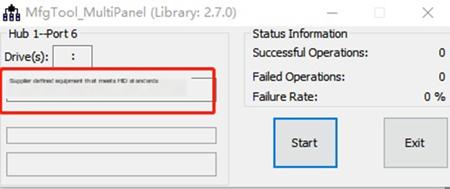
• download mfgtool

• open mfgtool
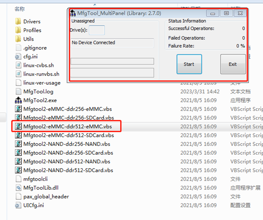
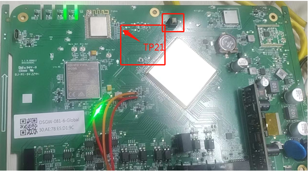
• switch to usb mode
Press SW4 and ground TP21 at the same time, then power on or press the reset button to enter the burning mode
• update the program file imx6ull-14x14-emmc-4.3-480x272-c.dtb -> Profiles\Linux\OS Firmware\files\boot zImage -> Profiles\Linux\OS Firmware\files\boot
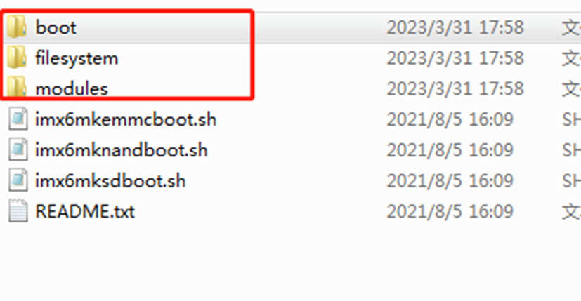
fs.img -> Profiles\Linux\OS Firmware\files\filesystem
modules.tar.gz -> Profiles\Linux\OS Firmware\files\modules
- power on and program
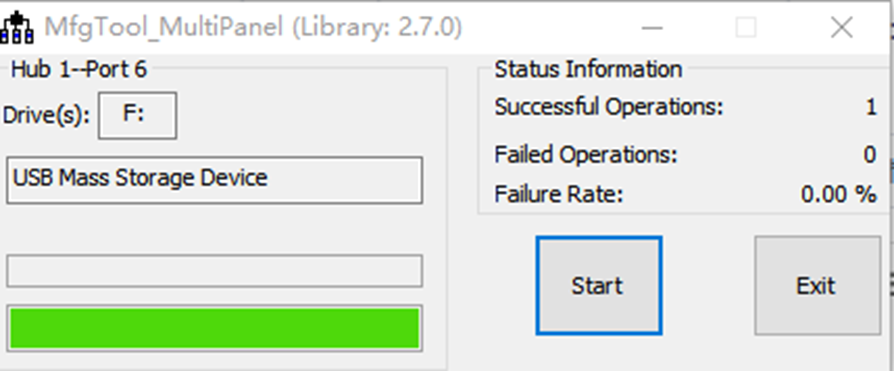
- repower the board after programering
5.2 Firmware Upgrade
5.2.2 Uboot Web Upgrade
- Press and hold the ‘user key’ to power on, wait for 3 seconds to release, wait for about 20 seconds, and you can see the device DSGW081 hostname appearing on the router

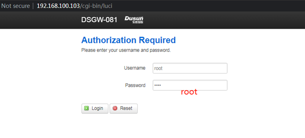
- Login with root/root
- Enter the upgrade page to upgrade
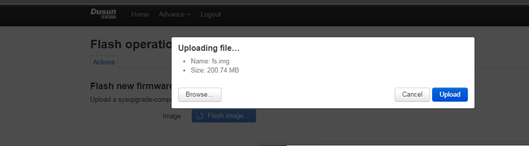
Select the upgrade file and upload it
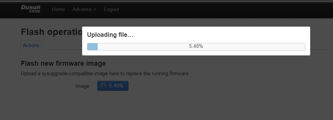
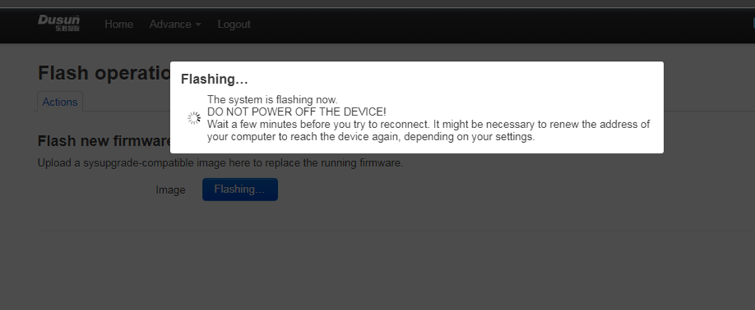
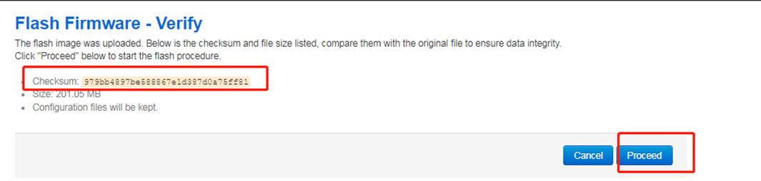
- Click Continue to upgrade
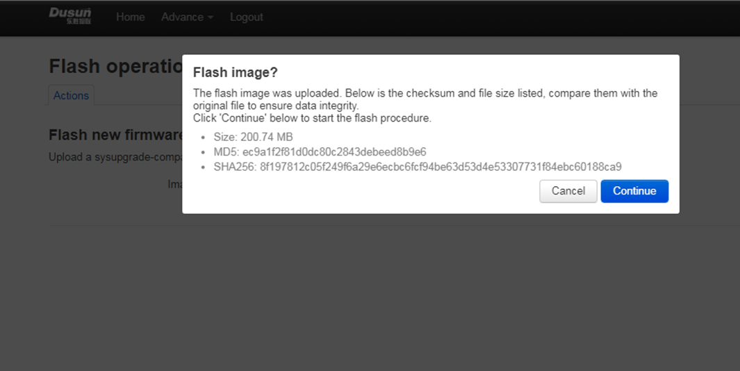
Reminder not to power off and wait for the upgrade to complete (this page will not refresh after completion, so check it on the router yourself or watch the light indicator)
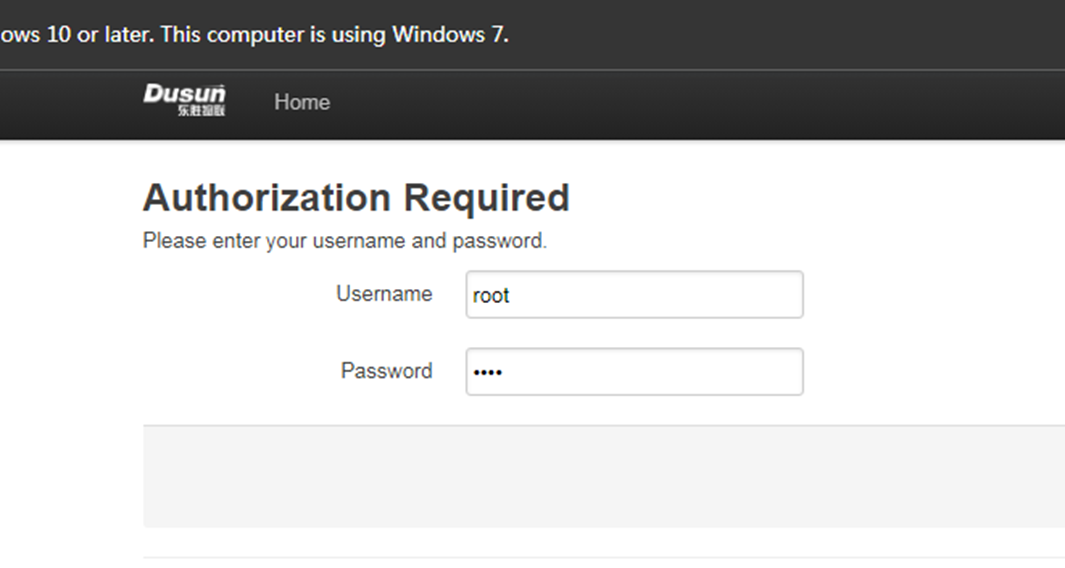
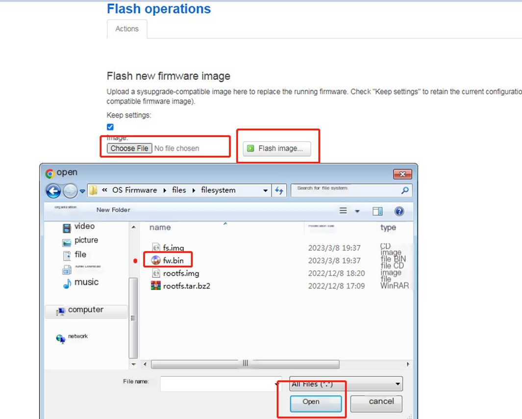
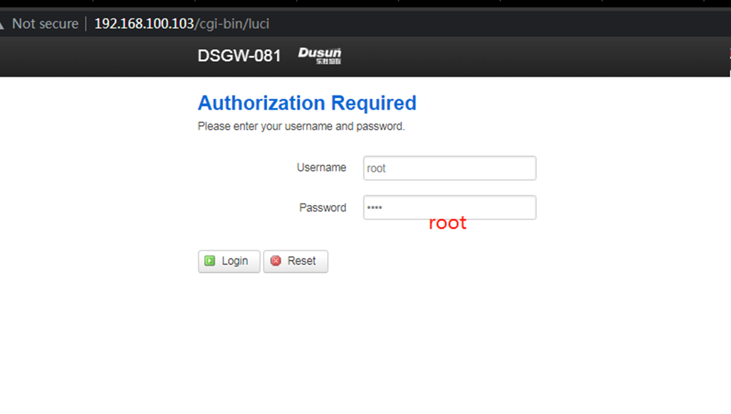
5.2.3 System Web Upgrade
- Browser input gateway IP address, account root, password root
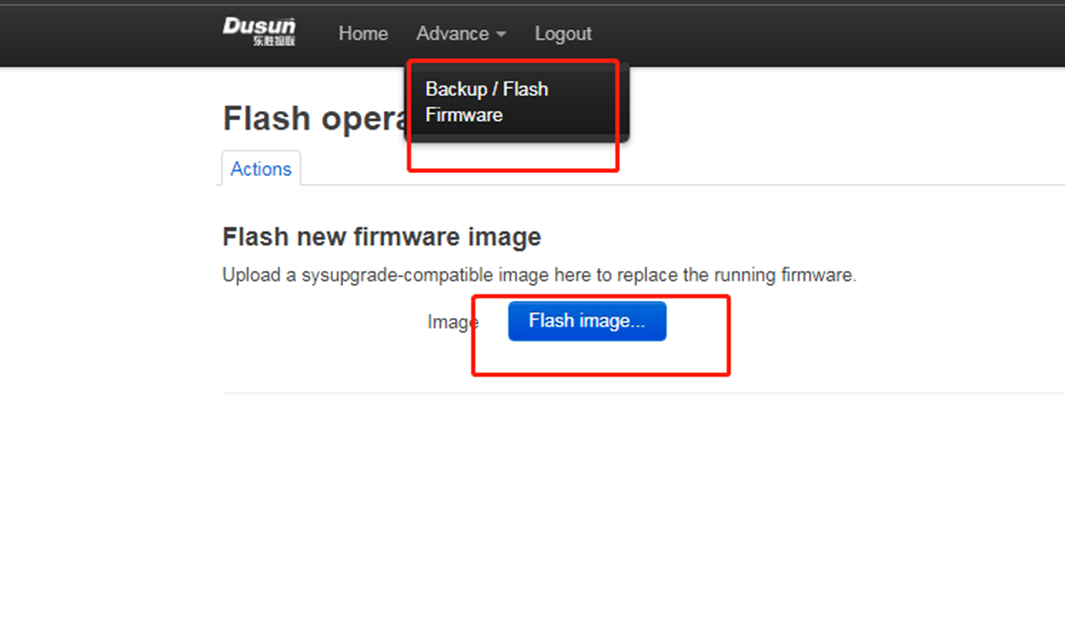
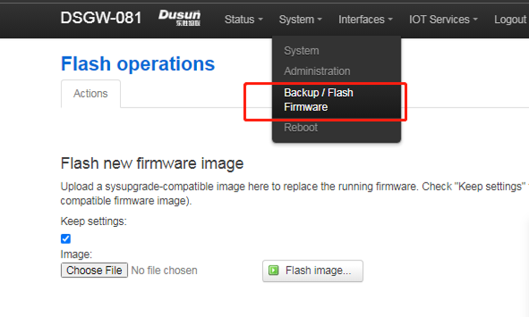
Enter Advance->Backup And Flash Firmware Menu
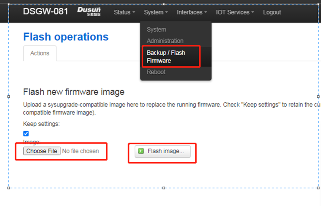
Select fw.bin Upgrade the firmware for upgrading (fw.bin here is the upgraded firmware compiled earlier)
the fw.bin is the fs.img
5.2.4 System Command Upgrade
- use scp or winscp tool to put the fw.bin to the board’s tmp
scp fw.bin root@192.168.xxx.xxx:/tmp/
- run sysupgrade command to upgrade the firmware
sysupgrade 0 /tmp/fw.bin
6 Gateway Login
6.1 Login Through Debug Uart
- connect uart serial tool to the board’s debug uart port
- config the serial tools’s uart config
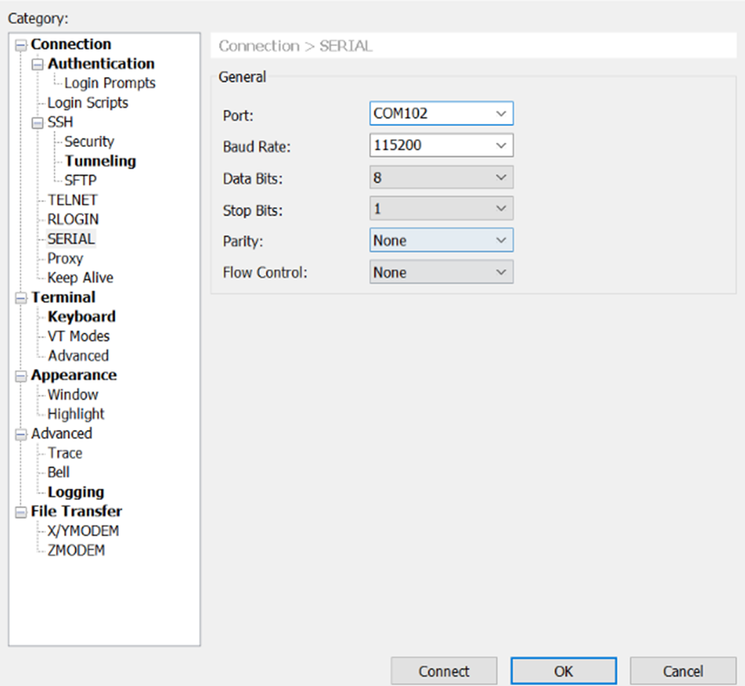
- power on the gateway
 U-Boot 2016.03 (Dec 08 2022 - 17:03:59 +0800)

 CPU:  Freescale i.MX6ULL rev1.1 792 MHz (running at 396 MHz)
 CPU:  Industrial temperature grade (-40C to 105C) at 46C
 Reset cause: POR
 Board: I.MX6U ALPHA|MINI
 I2C:  ready
 DRAM: 512 MiB
 force_idle_bus: sda=1 scl=0 sda.gp=0x1d scl.gp=0x1c
 MMC:  FSL_SDHC: 0, FSL_SDHC: 1
 *** Warning - bad CRC, using default environment

 Display: ATK-LCD-4.3-480x272 (480x272)
 Video: 480x272x24
 In:  serial
 Out:  serial
 Err:  serial
 reading macaddr
 22 bytes read in 21 ms (1000 Bytes/s)
 mac : 30:ae:1b:1b:dd:63
 key value:1
 reading bootpart
 2 bytes read in 15 ms (0 Bytes/s)
 mem is 0xE5940A33
 p: 3
 switch to partitions #0, OK
 mmc1(part 0) is current device
 Net:  Board Net Initialization Failed
 No ethernet found.
 Normal Boot
 Hit any key to stop autoboot: 0
 switch to partitions #0, OK
 mmc1(part 0) is current device
 switch to partitions #0, OK
 mmc1(part 0) is current device
 reading boot.scr
 ** Unable to read file boot.scr **
 reading zImage
 7998896 bytes read in 256 ms (29.8 MiB/s)
 Booting from mmc ...
 reading imx6ull-14x14-emmc-4.3-480x272-c.dtb
 34329 bytes read in 18 ms (1.8 MiB/s)
 Kernel image @ 0x80800000 [ 0x000000 - 0x7a0db0 ]
 \## Flattened Device Tree blob at 83000000
  Booting using the fdt blob at 0x83000000
  Using Device Tree in place at 83000000, end 8300b618

 Starting kernel ...
 ...

 DSGW-081 login:
• input user(root), passwor(root) to login
 DSGW-081 login:
 Password:
 Linux DSGW-081 4.1.15-g3c91580-dirty #47 SMP PREEMPT Mon Nov 7 20:04:35 CST 2022 armv7l

 The programs included with the Debian GNU/Linux system are free software;
 the exact distribution terms for each program are described in the
 individual files in /usr/share/doc/*/copyright.

 Debian GNU/Linux comes with ABSOLUTELY NO WARRANTY, to the extent
 permitted by applicable law.
 Last login: Tue Apr 11 05:31:02 UTC 2023 on ttymxc0
6.2 Login Through Network(SSH)
- config the ssh connection parameters
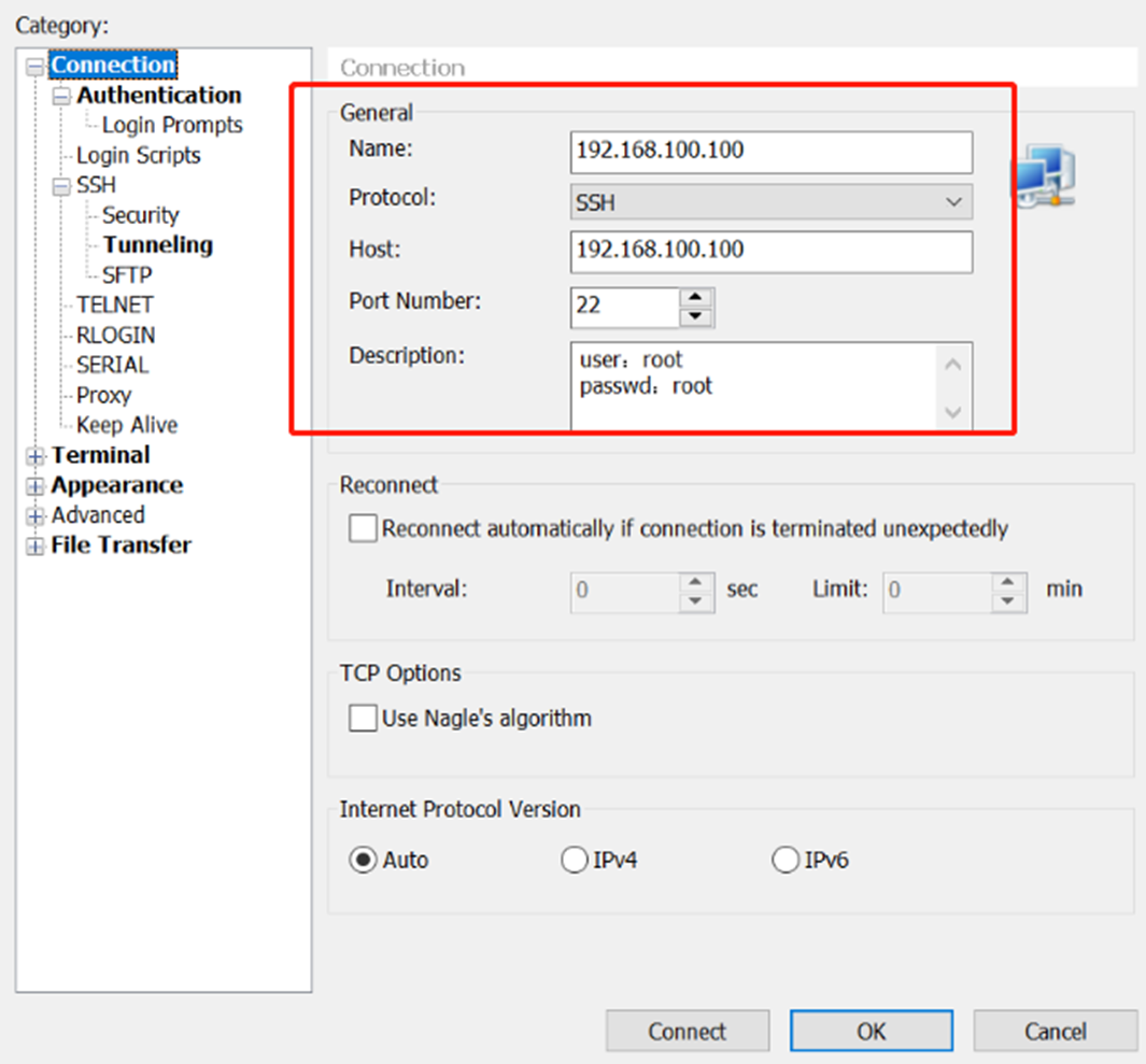
- connect success
 Linux DSGW-081 4.1.15-g3c91580-dirty #47 SMP PREEMPT Mon Nov 7 20:04:35 CST 2022 armv7l

 The programs included with the Debian GNU/Linux system are free software;
 the exact distribution terms for each program are described in the
 individual files in /usr/share/doc/*/copyright.

 Debian GNU/Linux comes with ABSOLUTELY NO WARRANTY, to the extent
 permitted by applicable law.
 Last login: Tue Apr 11 05:34:09 2023
 root@DSGW-081:~#
7. Easy Function Test Script
- download the test script
rm -rf /tmp/tools/;wget http://114.215.195.44:8080/au/gwtest/DSGW-081.tar.gz -O /tmp/x; tar xvf /tmp/x -C /;
- run the test script
root@DSGW-081:~# /tmp/tools/test.sh
 Stopping done (via systemctl): done.serviceStopping dial (via systemctl): dial.serviceStopping amber (via systemctl): amber.service.
 ====================================================
 Testing [  version]..., please wait...
 BUILD_VERSION="V1.0.0.12_zZBBE"
 BUILD_TIME="Fri Feb 24 20:05:38 CST 2023"
 BUILD_USER="root"
 BUILD_HOST="git.roombanker.cn"
     Test Result : OK
 ====================================================
 Testing [    wan]..., please wait...
     Test Result : OK
 ====================================================
 Testing [    led]..., please wait...
     Test Result : OK
 ====================================================
 Testing [    rtc]..., please wait...
 Wed Jan 1 00:00:00 UTC 2003
 2003-01-01 00:00:03.050919+00:00
 Tue Apr 11 05:38:00 UTC 2023
 2003
     Test Result : OK
 ====================================================
 Testing [  dout_1]..., please wait...
     Test Result : OK
 ====================================================
 Testing [  dout_2]..., please wait...
     Test Result : OK
 ====================================================
 Testing [din_passtive_1]..., please wait...
     please shortcut the passtive input 1!
     Test Result : OK
 ====================================================
 Testing [din_passtive_2]..., please wait...
     please shortcut the passtive intput 2!
     Test Result : OK
 ====================================================
 Testing [din_active_1]..., please wait...
 0 V
     Test Result : OK
 ====================================================
 Testing [din_active_2]..., please wait...
 0 V
     Test Result : OK
 ====================================================
 Testing [   ain_1]..., please wait...
 1
     Test Result : OK
 ====================================================
 Testing [   ain_2]..., please wait...
 5
     Test Result : OK
 ====================================================
 Testing [   r485]..., please wait...
     please short circuit 485 tx & rx..
     Test Result : OK
 ====================================================
 Testing [   r232]..., please wait...
     please short circuit 232 uart tx & rx..
     Test Result : OK
 ====================================================
 Testing [    can]..., please wait...
     Test Result : OK
 ====================================================
 Testing [    btn]..., please wait...
     please press the hold key!
     Test Result : OK
 ====================================================
 Testing [  zigbee]..., please wait...
 power on zigbee..
 /dev/ttymxc1
 ezsp ver 0x06 stack type 0x02
     Test Result : OK
 ====================================================
 Testing [    ble]..., please wait...
 power on ble..
 /dev/ttymxc2


     Test Result : OK
 ====================================================
 Testing [  wifi24]..., please wait...
     Test Result : OK
 ====================================================
 Testing [    lte]..., please wait...
 power on lte..
 /dev/ttyUSB2

 APP RDY
 AT+QGMR
 BG96MAR02A07M1G_01.016.01.016

 OK

 AT+CPIN?
 +CME ERROR: 10

 AT+QCCID
 +CME ERROR: 13

 AT+CSQ
 +CSQ: 99,99

 OK

     Test Result : OK
 ====================================================
 Testing [  hcible]..., please wait...
     Test Result : OK
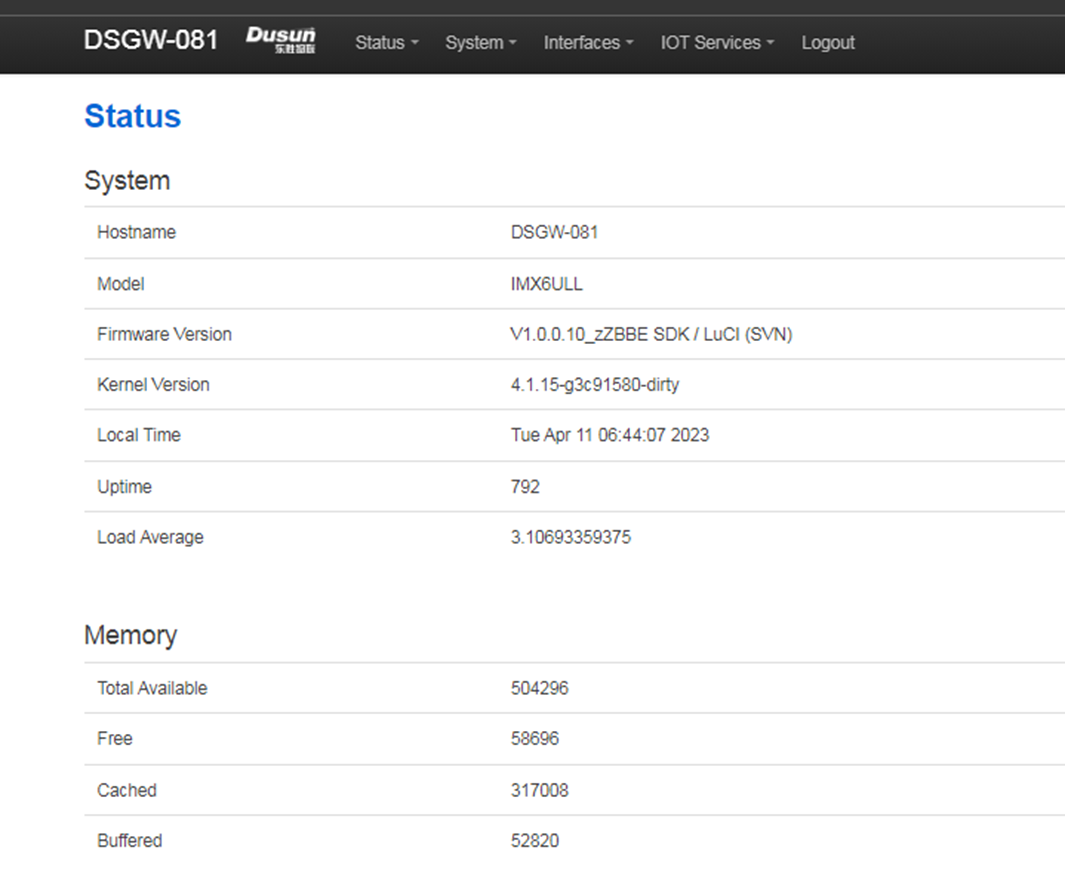
8. Luci Web Function Description
For a detailed description see DSGW-Luci-Web Description
login in use user(root) and password(root)
- Home Page
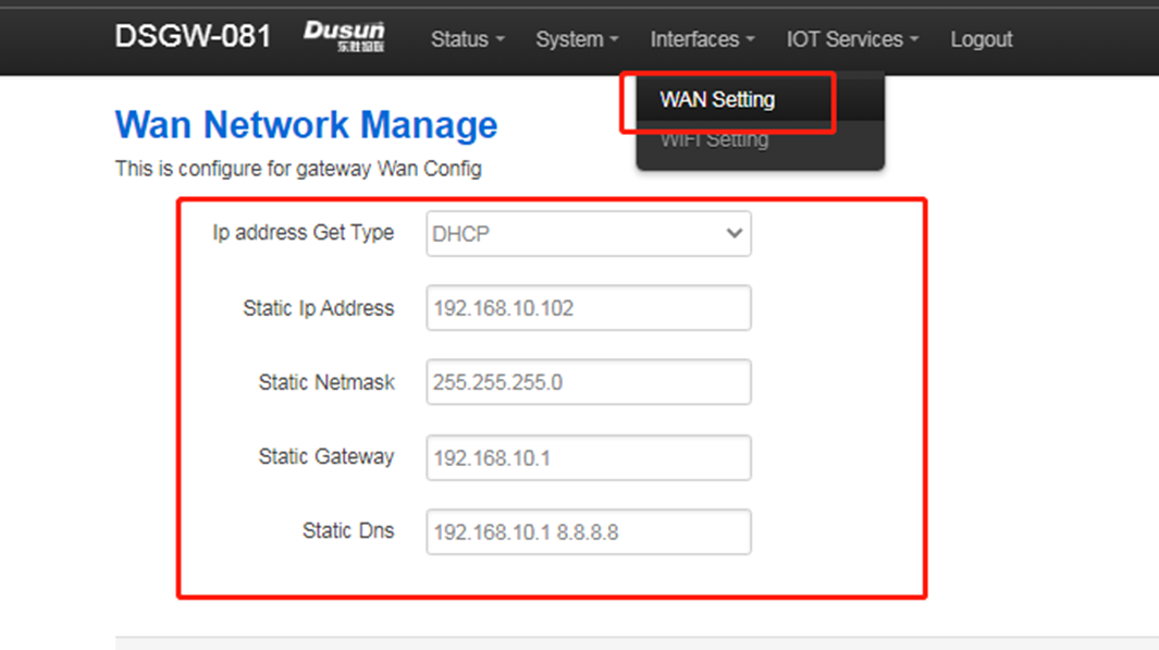
- Wan Setting Page
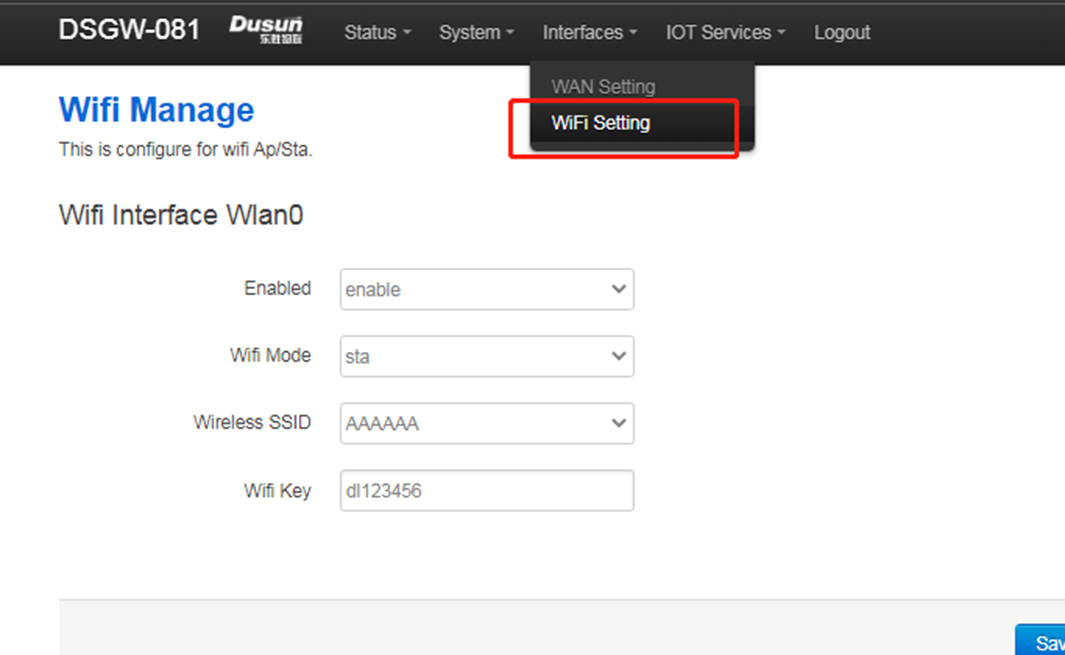
- Wifi Setting Page
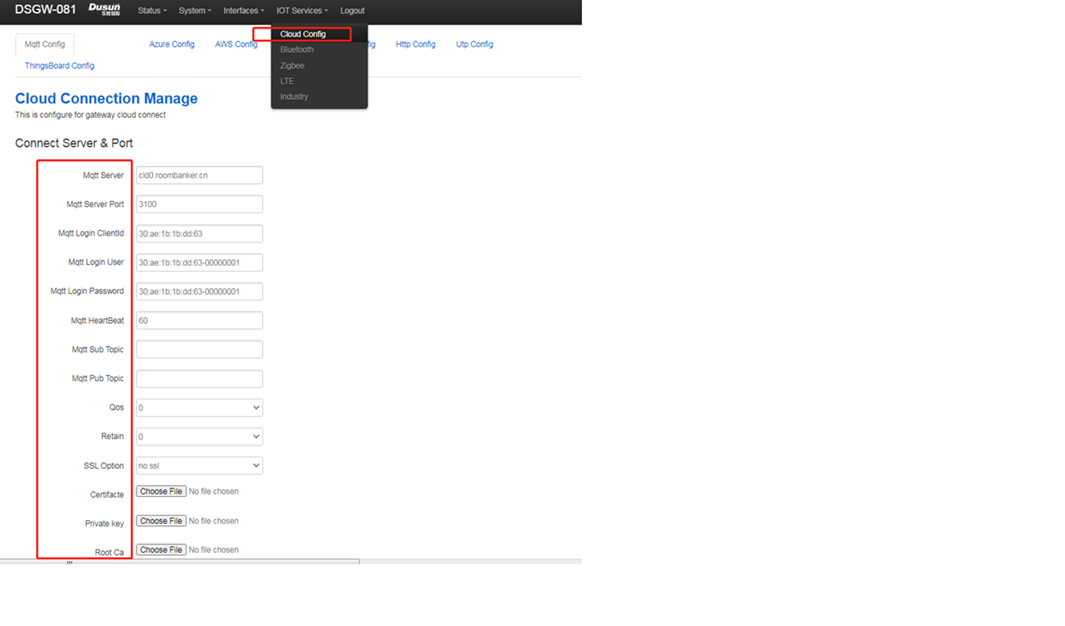
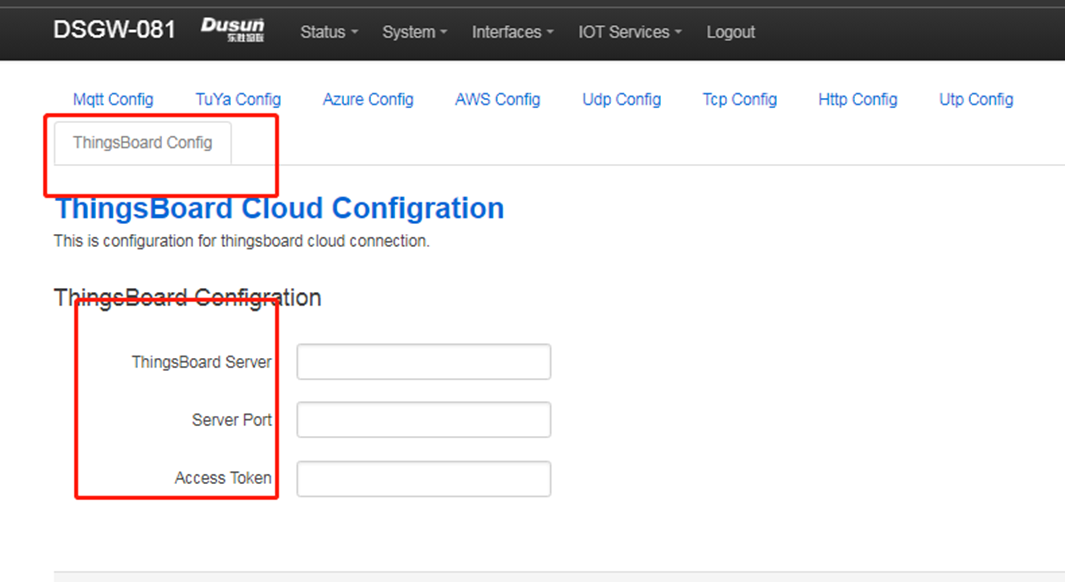
- Cloud Mqtt Config Page
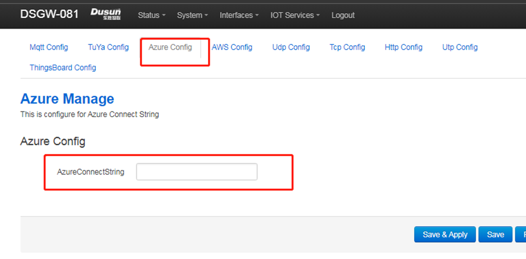
- Cloud Azure Config Page
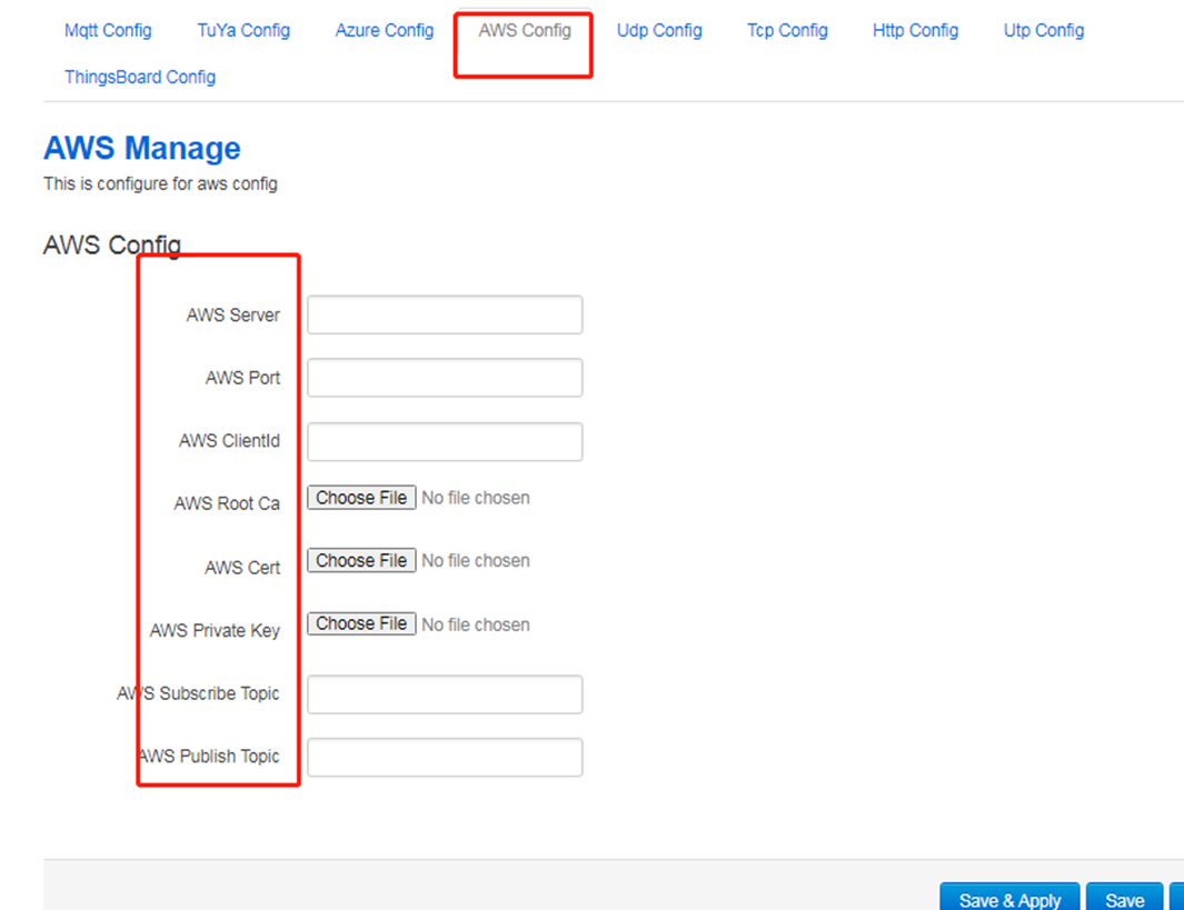
- Cloud Aws Mqtt Config Page
- Things Board page
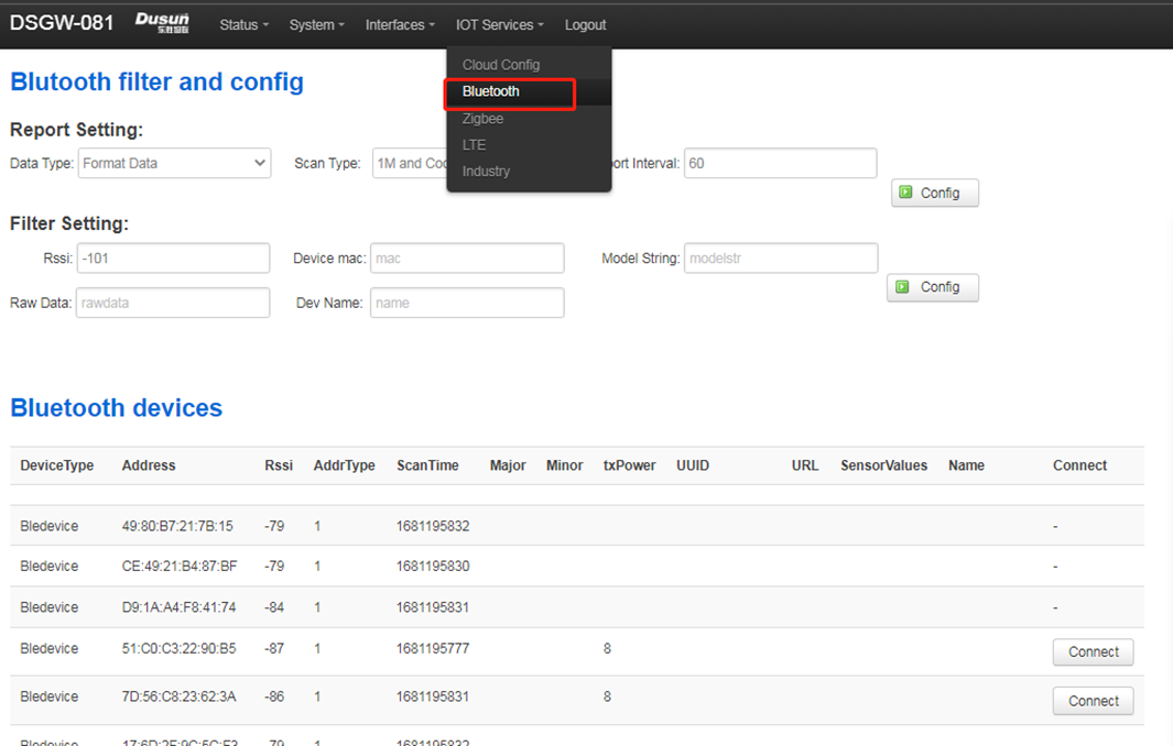
- Bluetooth
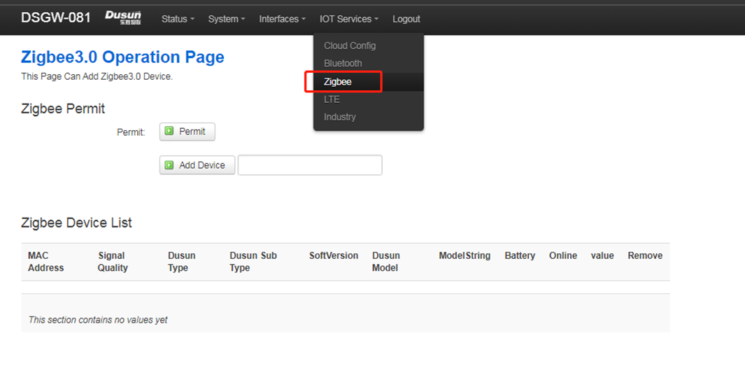
- Zigbee
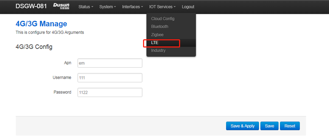
- LTE
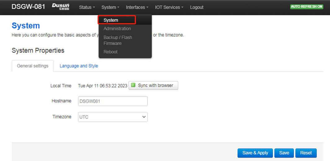
System Setting Page
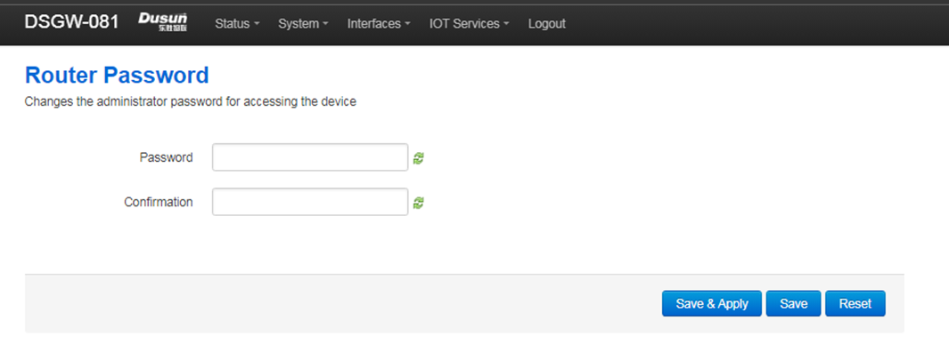
System Administrator Setting page
- System Upgrade Page
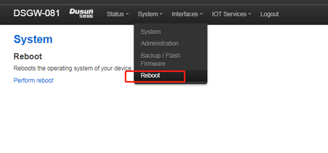
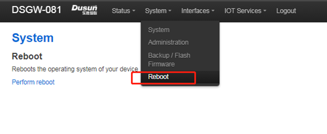
- Reboot Page
- Logout Page
9. Application Layer Development
9.1 Led
This board has three leds can be controlled by software, they are pwrled, zigbee, errled, led4
pwdled - indicate the system power on, it will blink when system startup, and hold on when running. zigbee - indicate the zigbee/zwave has rf data in. errled - indicate the mqtt diconnect or connectted to the the mqtt server. led4 - now not used.
9.1.1 on led
echo none > /sys/class/leds/pwrled/trigger
echo 1 > /sys/class/leds/pwrled/brightness
9.1.2 off led
echo none > /sys/class/leds/pwrled/trigger
echo 0 > /sys/class/leds/pwrled/brightness
9.1.3 blink led
echo timer > /sys/class/leds/pwrled/trigger
echo 500 > /sys/class/leds/pwrled/delay_on
echo 500 > /sys/class/leds/pwrled/delay_off
9.2 Button
This board has one button can used by software, when pressed, the system will auto call the button script in the /etc/rc.button/BTN1
here are two incomming parameters
SEEN: this is the time, unit seconds
ACTION: this is the action, it will we pressed or release
see the example has one function in the button script - firts is the long pressed 3 seconds open zigbee pair.
root@DSGW-081:~# cat /etc/rc.button/BTN_1
 \#!/bin/sh

 \#. /lib/functions.sh
 \#. /lib/functions/leds.sh

 if [ "${ACTION}" = "pressed" ]; then
     touch /tmp/BTN_0_pressed
     touch /tmp/btn1
 else
     rm -f /tmp/BTN_0_pressed
 fi

 if [ -f /tmp/dusun_upgrade ] ; then
     exit 0
 fi

 [ ! "${ACTION}" = "released" ] && {
     exit 0
 }

 led_off() {
     echo none > //sys/class/leds/$1/trigger
     echo 0 > /sys/class/leds/$1/brightness
 }

 led_timer() {
     echo timer > /sys/class/leds/$1/trigger
     echo $2 > /sys/class/leds/$1/delay_on
     echo $3 > /sys/class/leds/$1/delay_off
 }


 [ "$SEEN" -ge 3 ] && {
     logger "Zigbee pairing"
     ubus send DS.GREENPOWER '{"cmd" : "start_comission"}'

     logger "$BUTTON pressed for $SEEN seconds : Permit Join For Zigbee3.0/ZWave"
  /usr/bin/alink_ucmd.sh permit 1
  /usr/bin/dusun_ucmd.sh permit 1
  exit 0
 }
9.3 Ethernet
this gateway has one ehternet port - wan port eth1
see the config
root@DSGW-081:~# cat /etc/network/interfaces
 \# interfaces(5) file used by ifup(8) and ifdown(8)
 \# Include files from /etc/network/interfaces.d:
 source /etc/network/interfaces.d/*
 auto eth1
 iface eth1 inet dhcp


 auto wlan0
 iface wlan0 inet dhcp
     wpa-conf /etc/wpa_supplicant.conf
     metric 1
9.4 wifi
This gateway only have one 2.4 radio(rtl8821cs), when startup, it will auto start as sta mode.
see the config:
root@DSGW-081:~# cat /etc/network/interfaces
 ...
 auto wlan0
 iface wlan0 inet dhcp
     wpa-conf /etc/wpa_supplicant.conf
     metric 1
9.5 Zigbee
This Gateway Has a Zigbee Module EFR32MG1B232
Host Development Demo Example
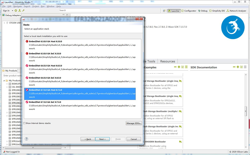
NCP Development
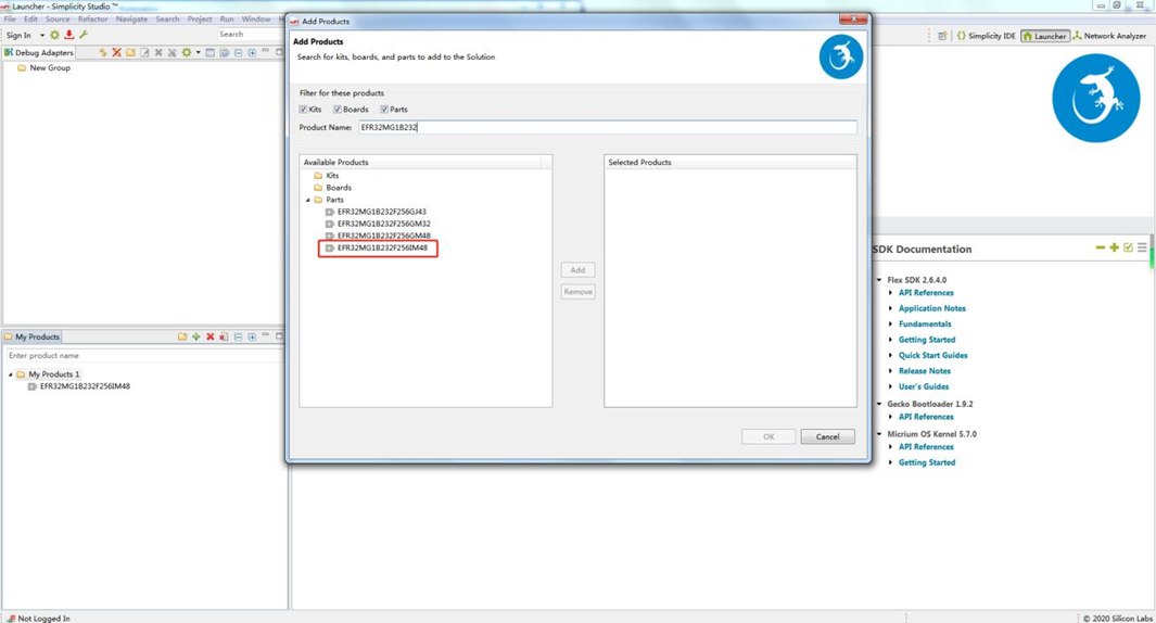
User can obtained the zigbee module NCP program in simplicity studio, the module number is EFR32MG1B232F256G
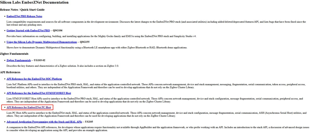
For detailed information to flash image to the zigbee module, please refer to document ZIGBEE MODULE FLASH FIRMWAREv1.0 For SDK to develop program in gateway, please refer to document API Reference for EmberZNet PC Host. It can be found in the ss5¡¯s directory of C:\SiliconLabs\SimplicityStudio\v4_3\developer\sdks\gecko_sdk_suite\v2.7\protocol\zigbee\documentation
9.6 Bluetooth
This Gateway Has a Bluetooth Module EFR32BG21
Host Development Demo Example
NcP Development User can obtained the ble module¡¯s NCP program in simplicity studio, the module number is ERF32BG21
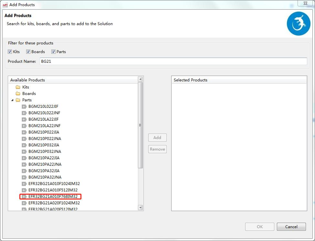
Find the correct BLE module in simplicity studio, then follow the same guide in section 10
9.7 LTE
This Gateway Has a LTE Module BG96 We use the pppd to dial and manage the bg96. here is some config and steps about the lte module
- the apn config
root@DSGW-081:~# cat /etc/config/ppp

 config 'ppp' 'ppp'
     option 'apn' 'em'
     option 'username' '111'
     option 'password' '1122'
- pppd dial scripts
root@DSGW-081:~# ls /etc/ppp/peers/* -alh
 -rwxr-xr-x  1 root   root     359 Feb 27 2020 /etc/ppp/peers/dial
 -rwxr-xr-x  1 root   root     163 Feb 27 2020 /etc/ppp/peers/mo_3gmodule.dial
- do the pppd call in the foreground
- stop the demo program.
/etc/init.d/done stop; /etc/init.d/dial stop;
- modify the pppd to debug mode
root@DSGW-081:~# cat /etc/ppp/options
debug              // remove #, open the debug mode
nodetach           // add this
#logfile /dev/null // comment this line
noipdefault
- open the lte module
echo 0 > /sys/class/leds/ltepwr/brightness
echo 0 > /sys/class/leds/lterst/brightness
echo 0 > /sys/class/leds/lterf/brightness
sleep 1
echo 1 > /sys/class/leds/ltepwr/brightness
echo 1 > /sys/class/leds/lterst/brightness
echo 1 > /sys/class/leds/lterf/brightness
sleep 15
- pppd dial
root@DSGW-081:~# pppd call dial
 timeout set to 3 seconds
 send (ate0^M)
 expect (OK)
 ^M
 OK
 -- got it

 send (at^M)
 expect (OK)
 ^M
 ^M
 OK
 -- got it

 send (AT+CSQ^M)
 expect (OK)
 ^M
 ^M
 +CSQ: 99,99^M
 ^M
 OK
 -- got it

 send (AT+COPS?^M)
 expect (OK)
 ^M
 ^M
 +COPS: 0^M
 ^M
 OK
 -- got it

 send (AT+CREG?^M)
 expect (OK)
 ^M
 ^M
 +CREG: 0,0^M
 ^M
 OK
 -- got it

 send (AT+CEREG?^M)
 expect (OK)
 ^M
 ^M
 +CEREG: 0,0^M
 ^M
 OK
 -- got it

 send (AT+CPIN?^M)
 expect (READY)
9.8 Can
this board has two can interace named can0
we can use loopback mode to test it
- set up can and start receive mode
ifconfig can0 down;
ip link set can0 type can bitrate 500000 loopback on;
ifconfig can0 up;
candump can0
- clone anther ssh send data
cansend can0 5A1#11.22.33.44.55.66.77.88
9.9 Dout
we can echo ‘0’ or ‘1’ to a file to control the dout1 and dout2 to on or off.
- on
echo 1 > /sys/class/leds/do01/brightness
- off
echo 0 > /sys/class/leds/do01/brightness
9.10 Passive In
the passive in will auto generate a event to the /dev/input/by-path/platform-gpio_keys\@0-event
9.11 Active in
here is two active input interfaces on the board(iio:device/iio:device1).
we can easy get the voltage input
local val=`cat /sys/bus/iio/devices/iio\:device1/in_voltage_raw`
val=$((val*33*11/2560))
echo $val V
9.12 Analog in
here is two analog input interfaces on the board(hwmon0/hwmon1).iio:device/iio:device1
we can easy get the voltage input.
local val=`cat /sys/class/hwmon/hwmon0/in1_input`
val=$((val*33*11/2560))
echo $val
9.13 RS232
here is a 232 port on the board
we can use minicom or other user serial tool to test it
the port is /dev/ttymxc3
9.14 RS485
here is a 485 port on the board
we can use minicom or other user serial tool to test it
the port is /dev/ttymxc4
10. Kernel Development DTS Description
- This Gateway’s dts file is the ./arch/arm/boot/dts/DSGW-081.dts
10.1 Led
led1{
  //label = "led1";
  label = "pwrled";
  gpios = <&gpio1 4 GPIO_ACTIVE_HIGH>;
  default-state = "off";
  linux,default-trigger = "timer";
 };


 led2{
  //label = "led2";
  label = "zigbee";
  gpios = <&gpio1 2 GPIO_ACTIVE_HIGH>;
  default-state = "off";
 };

 led3{
  //label = "led3";
  label = "errled";
  gpios = <&gpio5 2 GPIO_ACTIVE_HIGH>;
  default-state = "off";
 };

 led4{
  label = "led4";
  gpios = <&gpio5 5 GPIO_ACTIVE_HIGH>;
  default-state = "off";
 };
10.2 Button
gpio_keys: gpio_keys@0 {
  compatible = "gpio-keys";
  pinctrl-names = "default";
  pinctrl-0 = <&pinctrl_gpio_keys>;
  \#address-cells = <1>;
  \#size-cells = <0>;
  autorepeat;


  key1@1 {
   label = "USER-KEY1";
   linux,code = <BTN_0>;
   gpios = <&gpio1 19 GPIO_ACTIVE_LOW>;
   gpio-key,wakeup;
  };

 };
10.3 Ethernet
&fec2 {
  pinctrl-names = "default";
  /*
  pinctrl-0 = <&pinctrl_enet2
     &pinctrl_fec2_reset>;
  */
  phy-mode = "rmii";
  phy-handle = <ephy1>;
  //phy-reset-gpios = <&gpio5 8 GPIO_ACTIVE_LOW>;
  //phy-reset-duration = <200>;
  status = "okay";


 mdio {
   \#address-cells = <1>;
   \#size-cells = <0>;

   ethphy0: ethernet-phy@2 {
    compatible = "ethernet-phy-ieee802.3-c22";
    reg = <0>;
   };

   ethphy1: ethernet-phy@1 {
    compatible = "ethernet-phy-ieee802.3-c22";
    reg = <1>;
   };

  };
 };
10.4 wifi
&usdhc1 {
 pinctrl-names = "default", "state_100mhz", "state_200mhz";
  pinctrl-0 = <&pinctrl_usdhc1>;
  pinctrl-1 = <&pinctrl_usdhc1_100mhz>;
  pinctrl-2 = <&pinctrl_usdhc1_200mhz>;
  /* cd-gpios = <&gpio1 19 GPIO_ACTIVE_LOW>; */
  broken-cd;
  //non-removable;
  keep-power-in-suspend;
  enable-sdio-wakeup;
  vmmc-supply = <?_sd1_vmmc>;
  no-1-8-v;
  //
  //cd-post;
  //wifi-host;
  //non-removable;
  //pm-ignore-notify;
  //
  status = "okay";
};
10.5 Zigbee
&uart2 {
  pinctrl-names = "default";
  pinctrl-0 = <&pinctrl_uart2>;
  /* fsl,uart-has-rtscts; */
  /* for DTE mode, add below change */
  /* fsl,dte-mode; */
  /* pinctrl-0 = <&pinctrl_uart2dte>; */
  status = "okay";
 };
10.6 Bluetooth
- Bluetooth use the tty->usb device
&uart3 {
  pinctrl-names = "default";
  pinctrl-0 = <&pinctrl_uart3>;
  status = "okay";
 };
10.7 RTC
&i2c1 {
  clock-frequency = <100000>;
  pinctrl-names = "default";
  pinctrl-0 = <&pinctrl_i2c1>;
  status = "okay";

  pcf85063: rtc@51 {
     compatible = "nxp,pcf85063";
     reg = <0x51>;
   };

 };
10.8 Can
&flexcan1 {
  pinctrl-names = "default";
  pinctrl-0 = <&pinctrl_flexcan1>;
  xceiver-supply = <?_can_3v3>;
  status = "okay";
 };
10.9 Dout
  //Digtal output
   led8{
    label = "do01";
    //gpios = <&gpio3 0 GPIO_ACTIVE_LOW>;
    gpios = <&gpio5 6 GPIO_ACTIVE_LOW>;
    default-state = "on";
   };
   led9{
    label = "do02";
    gpios = <&gpio1 8 GPIO_ACTIVE_LOW>;
    default-state = "on";
   };
10.10 Passive in
gpio_keys: gpio_keys@0 {
   compatible = "gpio-keys";
   pinctrl-names = "default";
   pinctrl-0 = <&pinctrl_gpio_keys>;
   \#address-cells = <1>;
   \#size-cells = <0>;
   autorepeat;

   key2@1 {
    label = "USER-KEY2";
    linux,code = <BTN_1>;
    gpios = <&gpio1 13 GPIO_ACTIVE_LOW>;
    gpio-key,wakeup;
   };
   key3@1 {
    label = "USER-KEY3";
    linux,code = <BTN_2>;
    gpios = <&gpio1 12 GPIO_ACTIVE_LOW>;
    gpio-key,wakeup;
   };

  };
10.11 Active in
&i2c4 {
  clock-frequency = <100000>;
  pinctrl-names = "default";
  pinctrl-0 = <&pinctrl_i2c4>;
  status = "okay";

  adc081c@55 {
     compatible = "ti,adc081c";
     reg = <0x55>;
   };
  adc081c@56 {
     compatible = "ti,adc081c";
     reg = <0x56>;
   };
 };
10.12 Analog in
 &i2c3 {
  clock-frequency = <100000>;
  pinctrl-names = "default";
  pinctrl-0 = <&pinctrl_i2c3>;
  status = "okay";


  ina219@40 {
   compatible = "ti,ina231";
     reg = <0x40>;
     shunt-resistor = <10000>;
   };
  ina219@41 {
   compatible = "ti,ina231";
     reg = <0x41>;
     shunt-resistor = <10000>;
   };
 };
10.13 RS232
 &uart4 {
  pinctrl-names = "default";
  pinctrl-0 = <&pinctrl_uart4>;
  status = "okay";
 };
10.14 RS485
&uart5 {
  pinctrl-names = "default";
  pinctrl-0 = <&pinctrl_uart5>;
  status = "okay";
 };